Variable Frequency Drives (VFDs) vary the speed of the motors reducing the amount of torque transferred. The VFD reduces motor speed to the minimum needed setting, reducing energy consumption. Likewise, it will increase application of motor speed as more cases are demanded in the fill room. Savings are achieved by installing a VFD to reduce speed and electrical power when not needed while reducing wear associated with unneeded movement.
Motors that are used for applications where motor speed varies. Examples include trim air compressors, fans, and pumps.
The information needed to develop an install VFD on fan motor recommendation are motor nameplate data of fans, live readings of fan motor (if this information can be obtained), datalog information (if able to datalog), fan type (forced draft or induced draft), current fan control type (outlet damper or inlet vane), the fan's flow capacity and its respective percentage of time (obtained through conversations with facility personnel), and the fan motor operation data (usually obtained from discussion with facility personnel.
The first step in developing this recommendation is to fill out a Motor Analysis Tool (MAT) for each of the proposed motors to obtain its Power Input and Energy Consumption. This can be done with either the nameplate data and live readings information, just the nameplate data, or datalogger information. The steps for this can be seen in the Turning Off Idle Motors: Case 1(Nameplate Data Available) and Case 2(Nameplate Data and Live Reading Available).
Once you have inputted all the information onto the MAT Tool, we will now use the Fan Control Analysis Tool which can be downloaded from: Google Drive --> OSU EEC Template Directory --> Best Templates --> Fan Control Analysis Tool --> fcat.analysis tool.xlsx
Using this template, we import the information obtained from the MAT Tool onto the FCAT Tool
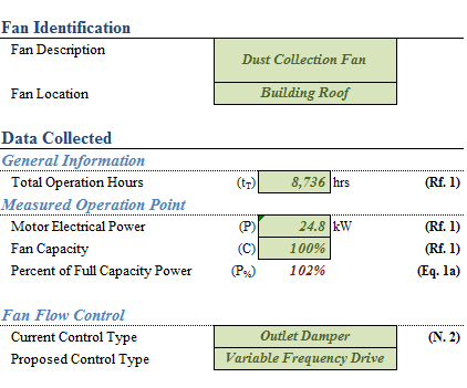
Figure 1: FCAT Page 1
On the next page, input the Flow Capacity and its respective Percent of Time. Without a datalogger, this is usually obtained through conversations with facility personnel (whether its by estimates or looking at an operation log).

Figure 2: FCAT Page 2
Lastly, fill out the missing information on the Analysis Tab. The Incremental Electricity cost is obtained once the Utility Analysis is done. The Implementation Cost Analysis is automatically inputted based on the Fan Motor Horsepower (referenced from VFD Cost Estimate Table tab).
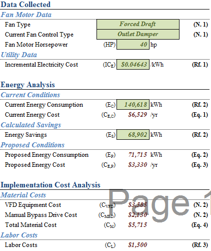
Figure 3: Analysis Tab
Notice the cells B5 (Fan Type) and B6 (Current Fan Control Type) are drop down menus. This is used to indicate what existing fan type and fan controls are used in the facility.
The savings of this recommendation comes from the difference in power of the fan control.
Finally, do not forget to fill out the Narrative, Incentives, and Financial Analysis tab!
The first step is to fill out the MAT Tool once again, but this time, after filling in the motor nameplate data, the Datalog Analysis tab needs to be filled out as well. This is where you copy paste the HOBO Time Stamp and HOBO Measured Amps obtained from your HOBO Datalogger.

Figure 4: Datalog Analysis Tab
Once you have inputted all the information onto the MAT Tool, we will now use the Fan Control Analysis Tool which can be downloaded from: Google Drive --> OSU EEC Template Directory --> Best Templates --> Fan Control Analysis Tool --> fcat.analysis tool.xlsx
Using this template, we import the information obtained from the MAT Tool onto the FCAT Tool, much like Case 1 and Case 2. However, the difference with Case 3 is the Flow Capacity and Percent of Time inputs. Instead of inputting values based on facility personnel conversations, this will be obtained from the MAT Bin Analysis Tab.
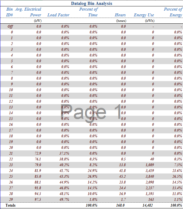
Figure 5: MAT Bin Analysis Tab
Notice load factor does not equal flow capacity. Flow capacities were developed using the bin analysis of observed motor operation and the performance data which comprises the chart below. Use basic interpolation for power values between flow points.

Figure 6: FCAT Page 2
Lastly, fill out the missing information on the Analysis Tab. The Incremental Electricity cost is obtained once the Utility Analysis is done. The Implementation Cost Analysis is automatically inputted based on the Fan Motor Horsepower (referenced from VFD Cost Estimate Table tab).
The savings of this recommendation comes from the difference in power of the fan control.
Finally, do not forget to fill out the Narrative, Incentives, and Financial Analysis tab!